| HOME |  |
MG TF 115 Home Page |
 |
MG TF 'THE CAR' |
| CENTRAL LOCKING | REAR SPEAKERS |
| DOOR MIRRORS | CHEATER COVERS | REAR GRILL | ||
| ICE & SATNAV | HANDS FREE PHONE | BOOT RELEASE |
| HOME |  |
MG TF 115 Home Page |
 |
MG TF 'THE CAR' |
| CENTRAL LOCKING | REAR SPEAKERS |
| DOOR MIRRORS | CHEATER COVERS | REAR GRILL | ||
| ICE & SATNAV | HANDS FREE PHONE | BOOT RELEASE |
General Up to and including model year 2004, the TF 115 came without remote central locking as standard. All the cabling and connectors are in place for central locking but the door latches do not contain the necessary motors and gears and the ecu does not have the central locking functions programmed. To fit central locking involves changing the door latches and, if necessary, re-programming the ecu. Tools required for the job are:-
Parts required for the job are:-
|
||
Driver Side Latch Shown right is the non-central locking latch fitted as standard to the TF 115. It is the same as a central locking latch except that there is no central locking motor/gearing in the housing. Curiously it carries the same part number as the central locking version i.e. FQJ102262PMA. |
|
|
Passenger Side Latch This is the same as the driver's side latch except it is handed with a single five wire cable terminated in a connector and the external handle operating rod securing clip is red (green for the driver's side latch). This differs from the 'central locking' latch in that there is no external lock operating rod or lever on the 'central locking' latch as there is no lock barrel on the passenger side of those cars fitted with central locking as standard. Again, it carries the same part number as the central locking version i.e. FQJ102271PMA. |
|
|
Latch Removal The removal is the same for both driver and passenger side latches as follows:- 1. Remove the internal handle trim surround (single screw). 2. Remove the door pull insert (two screws). 3. Remove the three screws from the door trim (one at front top and two on the rear edge of the door trim). 4. Starting at the bottom centre, ease the door trim away from the door such that the trim securing clips 'pop' out of their locations. There are six securing clips along the bottom and front edges of the trim. 5. Lift the rear of the door trim over the internal locking button and then slide it towards the back of the door such that the front clears the door mirror housing and lift up and clear. 6. Undo the two screws securing the internal door handle assembly to the door and pull the assembly clear. Rotate the operating cable locking clip to release the operating cable end and unclip the cable from the 'fork' on the assembly to completely separate the cable from the handle assembly. 7. Carefully peel away the internal protective membrane (polythene sheet) from the rear half of the door such that access to the door latch can be obtained. You may find it helpul to fold this membrane back and tape it temporarily to the front half of the door out of harms way. 8. Unclip the operating cable from the two clips holding it to the door. 9. Unclip the cable harnesses (white clips at bottom rear of door - two for the driver's side, one for the passenger's side) running to the latch in the base of the door, lift up the connectors and separate the connector halves. |
||
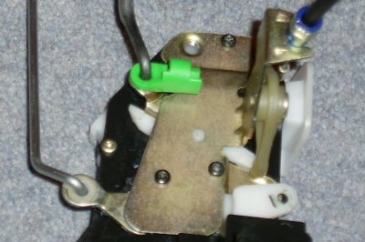
10. Release the external handle operating rod from the latch by rotating the green clip clockwise (see photograph right) and disengaging the rod from the lever. For the passenger side latch the red clip needs to be rotated anticlockwise. |
 |
|
11. From the rear end face of the door unscrew and remove the three Torx head bolts (T25) securing the latch to the door. The remaining operating rods attached to the levers will take the weight of the latch and prevent it falling into the door. 12. With a bit of effort the internal locking button operating lever can be disengaged from the latch lever but, try as I might, I could not manouevre the latch to disengage the external lock operating lever. To do this either remove the external door handle assembly from the door or proceed as follows (which, if you are careful, is quicker and retains the adjustment on the operating rods). |
||
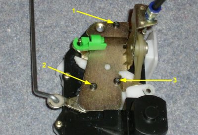
13. Working inside the door hold the latch assembly such that the cover plate is held firmly against the latch body. Carefully unscrew and remove the three Torx head screws (T10) holding the brass cover plate in place (see photograph right). Note: It is advisable to magnetise the screwdriver in order that the screws 'stick' to the screwdriver and do not drop into the door. Also note that these screws are cross head rather than Torx on some older versions. |
 |
|
14. Very carefully remove the cover plate, complete with operating cable, and put aside. 15. Supporting the latch assembly, remove the three levers to free it completely. The internal locking button and operating rod with lever can be removed by pulling it down and out from inside the door. Remove the latch assembly by keeping it upright and rotating the motor housing around the door window rear guide rail and withdraw it from the door. 16. The existing levers can be left or can replaced with the new levers from the central locking latches to be fitted. Note that the passenger side external lock operating rod and lever are not required so can be removed completely. This will require the external door handle assembly to be removed from the door in order to remove the operating rod. Otherwise the rod can be secured out of the way onto the door strengthening beam e.g. by the use of a couple of cable ties. |
||
| Latch
Installation
Basically this is a straight reversal of removal and is the same for both driver and passenger side latches as follows:- 1. With the replacement 'central locking' latch laying flat on a clean surface, undo the three Torx head screws (T10) holding the brass cover plate in place and carefully remove the plate complete with operating cable. |
||
2. Study the positions of the levers under the cover plate such that they can be reassembled correctly in-situ later on. The photograph right shows the positions of the levers for the driver's side latch - latch open. The passenger side latch will be similar except that it will be handed the other way and the external locking lever and connecting rod will not be present. |
|
|
3. Remove the levers from the latch assembly and 'clip' them onto the operating rods (unless you are using the existing levers, in which case put them to one side). 4. Holding the latch assembly upright rotate it around the door widow guide rail and into the door. 5. Whilst supporting the latch assembly feed the internal locking button and rod up through its location hole in the top of the door frame and locate its lever into the latch assembly. Locate the other two levers (or one in the case of the passenger side) into the latch assembly. |
||
6. Whilst still supporting the latch assembly refit the brass cover plate, complete with operating cable, back onto the latch assembly and re-fit and tighten the three Torx head screws (T10). Note: When re-fitting the cover plate ensure that the plastic lever of the operating cable lips under the plastic lever in the latch (see photograph right). |
 |
|
7. Engage the external handle operating rod into its lever and secure by roating the green clip anticlockwise to lock the rod in place (red clip clockwise on the passenger side). The latch will now be supported on the operating rods. 8. Thread the operating cable back through the internal door membrane and re-fit the operating cable to the internal handle assembly ensuring that the outer is located firmly in the 'fork' and that the locating clip is rotated back and clicks into place to secure the inner cable. 9. Loosely fit the internal handle assembly back to the door (two screws) ensuring the two tabs on the rear edge of the assembly are located into their respective slots on the door. 10. Line up the latch assembly with its locating holes and re-fit the three T25 Torx bolts and tighten to secure the latch firmly back in place. 11. Mate the connector halves on the cables (two on the driver side, one on the passenger side) and clip the cables back to the inside of the door ensuring the cables are not in the way of the door window guides. 12. Carefully shut the door and check the latch functions correctly including operation of the external handle, internal handle, locking button and alarm. 13. If all works OK then re-secure the internal membrane to the inside of the door. 14. Re-fit the door trim by locating the front of the top 'lip' into the window channel (this is easier if the window is down) and sliding it forward such that the front slides under the wing mirror housing. Locate the internal locking button through its hole in the door trim and re-seat the door trim fully onto the door. Relocate each of the trim securing clips with a sharp push. Refit the three trim screws and the door pull insert (two screws). 15. Line up the internal door handle assembly such that it sits square in the aperture within the door trim and fully tighten the two locating screws. 16. Re-fit the internal handle trim surround (single screw). 17. Perform a final functional test to make sure all is working correctly. |
||
| Finally
The latches are now fitted but the central locking may not function until the ecu is re-programmed. Book it in to the dealers who will use the MG Test Book programme to set the central locking operational. To do this the car must be logged on and identified as having central locking - this will then give access to the central locking options which can be selected and the car re-programmed accordingly. The car, all being well, should now have fully functioning central locking operated from the remote fob. Enjoy! |
||